Adding a Physical Button Input
Now that you have a configurable OpenLCB node with CAN transport, let’s add physical hardware interaction. We’ll start with a pushbutton input that produces OpenLCB events when pressed and released.
What You’ll Build
In this section, you’ll:
- Wire a pushbutton to GPIO 18
- Configure a
ConfiguredProducerto monitor the button state - Use
RefreshLoopfor efficient 33Hz polling with hardware debounce - See the button produce unique event IDs when pressed and released
- Configure the button’s behavior through JMRI/LccPro
Additional Hardware Required
For this section, you’ll need:
- 1× Tactile pushbutton switch (normally-open, momentary contact)
- Jumper wires (you already have these from Chapter 5)
Note: The ESP32 has internal pull-up resistors, so you don’t need external resistors for button inputs. We’ll use pull-up (rather than pull-down) configuration—see the “Active-Low vs Active-High” section below for why.
Hardware Setup
Breadboard Wiring
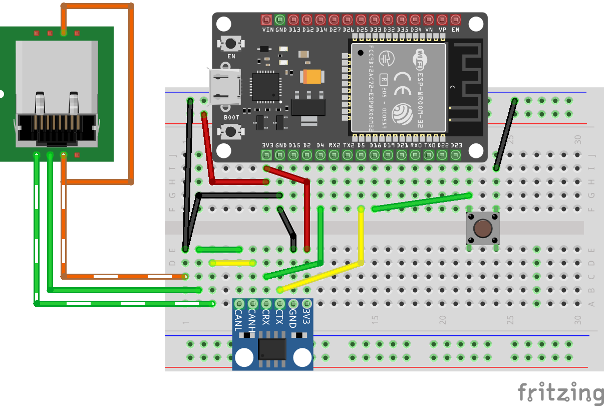
Figure: ESP32 with CAN transceiver and pushbutton on breadboard
Connect the button as follows:
- One side of button → GPIO 18
- Other side of button → GND
That’s it! The ESP32’s internal pull-up resistor will keep GPIO 18 HIGH when the button is not pressed.
How It Works
- Button released (unpressed): Internal pull-up resistor pulls GPIO 18 HIGH (3.3V) → produces “Event On”
- Button pressed: Direct connection to GND pulls GPIO 18 LOW (0V) → produces “Event Off”
This is called active-low logic: pressing the button creates the LOW state.
Note: This may seem reversed—you might expect pressing a button to produce “Event On” rather than “Event Off”. We’ll explain why we use this pull-up configuration (and why we don’t use pull-down to make it more intuitive) in the “Active-Low vs Active-High” section below.
Understanding the Code Changes
We’ll add three key components to make the button work:
1. GPIO Pin Definition (before OpenMRN stack initialization)
+// Define GPIO pin for button input (active-low with internal pull-up)
+// When button is pressed, pin reads LOW (0); when released, reads HIGH (1)
+GPIO_PIN(BUTTON, GpioInputPU, 18);
+
+// GPIO initializer - sets up all GPIO pins before OpenMRN stack starts
+typedef GpioInitializer<BUTTON_Pin> GpioInit;
Key points:
GpioInputPUenables the internal pull-up resistor (see “Active-Low vs Active-High” section for why we use pull-up)- The pin must be initialized before the OpenMRN stack starts
GpioInit::hw_init()will be called insetup()beforeopenmrn.begin()
2. Configuration in config.h
Add a ProducerConfig entry to the CDI segment:
 CDI_GROUP_ENTRY(blink_interval, Uint16ConfigEntry,
                 Default(1000),
                 Min(100),
                 Max(30000),
                 Name("Blink Interval"),
                 Description("Milliseconds between alternating events (100-30000)"));
+CDI_GROUP_ENTRY(button, ProducerConfig,
+                Name("Button 1"),
+                Description("Physical button input on GPIO 18"));
 CDI_GROUP_END();
This creates a configuration section for the button with:
- Description: User-editable label for this input
- Event On: Event ID produced when button is released (pin goes HIGH)
- Event Off: Event ID produced when button is pressed (pin goes LOW)
- Debounce: Number of polling cycles the input must remain stable
3. Producer and Refresh Loop
 } factory_reset_helper;

+// Button producer - monitors GPIO 18 and produces events on state changes
+// Uses RefreshLoop for 33Hz polling (debounce handled by ConfiguredProducer)
+openlcb::ConfiguredProducer button_producer(
+    openmrn.stack()->node(), cfg.seg().button(), BUTTON_Pin());
+
+// RefreshLoop - polls button at 33Hz and handles debouncing
+openlcb::RefreshLoop button_refresh_loop(openmrn.stack()->node(),
+    {button_producer.polling()});
+
 void init_serial() {
How it works:
RefreshLooppolls the button at 33Hz (~30ms per cycle)- Each poll calls
button_producer.polling()which:- Reads the current GPIO state
- Compares it to the previous state
- If different for
debounceconsecutive cycles → state change confirmed - Produces the appropriate event (On or Off)
4. Factory Reset Updates
Initialize the button configuration with default values:
 void factory_reset(int fd) override
 {
     // Initialize SNIP dynamic data on first boot
     // This data is displayed by JMRI in the node properties dialog
     cfg.userinfo().name().write(fd, openlcb::SNIP_NODE_NAME);
     cfg.userinfo().description().write(fd, openlcb::SNIP_NODE_DESC);

     // Initialize application settings with defaults
     cfg.seg().blink_enabled().write(fd, 1);      // Default enabled
     cfg.seg().blink_interval().write(fd, 1000);  // Default 1 second

+    // Initialize button producer configuration
+    // Event IDs use NODE_ID base with unique offsets to avoid collision
+    cfg.seg().button().description().write(fd, "Button 1");
+    cfg.seg().button().event_on().write(fd, NODE_ID + 0x0100);   // Released (HIGH)
+    cfg.seg().button().event_off().write(fd, NODE_ID + 0x0101);  // Pressed (LOW)
+    CDI_FACTORY_RESET(cfg.seg().button().debounce);  // Default: 3 (90ms at 33Hz)
+
     Serial.println("Factory reset: wrote defaults (blink_enabled=Enabled, blink_interval=1000 ms)");
+    Serial.printf("Button events: ON=0x%016llX, OFF=0x%016llX\n",
+                  NODE_ID + 0x0100, NODE_ID + 0x0101);
 }
Event ID strategy:
- Base all event IDs on
NODE_IDto ensure uniqueness
We use offset +0x0100 for button ON (released) and +0x0101 for button OFF (pressed). The higher offset provides visual separation from async_blink events and makes button events easy to identify in event IDs. This is just one approach—use whatever offset scheme works for your node.
5. Setup() Initialization
Add GPIO initialization before starting the OpenMRN stack:
 void setup() {
   init_serial();
   init_filesystem();

+  // Initialize GPIO pins before OpenMRN stack starts
+  // This ensures pins are in known state before producers/consumers access them
+  GpioInit::hw_init();
+  Serial.println("GPIO initialized: Button on GPIO 18 (active-low with pull-up)");
+
   can_driver.hw_init();
   init_openlcb_stack();
   openmrn.add_can_port_select("/dev/twai/twai0");
Critical: GPIO must be initialized before openmrn.begin() so the producer has a valid pin state to read.
Complete Working Code
The complete working code at this point is available on GitHub:
- PlatformIO version: code/platformio/chapter6/v2_button/
- Arduino IDE version: code/arduino/chapter6/v2_button/
You can download or clone the repository and open either version to get the exact code with the button input implemented.
Building and Flashing
Update CANONICAL_VERSION
Since we’re adding a new configuration field, increment the version number in config.h:
 /// Version number for the configuration structure
-static constexpr uint16_t CANONICAL_VERSION = 0x0003;
+static constexpr uint16_t CANONICAL_VERSION = 0x0004;
This triggers a factory reset on first boot, initializing the new button configuration.
Build, Flash, and Monitor
Use PlatformIO’s “Upload and Monitor” task:
- Click the PlatformIO icon in the left sidebar
- Expand async_blink_esp32 → esp32doit-devkit-v1 → General
- Click Upload and Monitor
Expected Serial Output
=== OpenLCB async_blink ESP32 Example ===
Node ID: 0x050201020200
Event 0: 0x0502010202000000
Event 1: 0x0502010202000001

Initializing SPIFFS...
SPIFFS initialized successfully
GPIO initialized: Button on GPIO 18 (active-low with pull-up)
ESP-TWAI: Configuring TWAI (TX:5, RX:4, EXT-CLK:-1, BUS-CTRL:-1)

Creating CDI configuration descriptor...
[CDI] Checking /spiffs/cdi.xml...
[CDI] File /spiffs/cdi.xml is not up-to-date
[CDI] Updating /spiffs/cdi.xml (len 2509)
[CDI] Registering CDI with stack...
Initializing OpenLCB configuration...
Factory reset: wrote defaults (blink_enabled=Enabled, blink_interval=1000 ms)
Button events: ON=0x0000050201020300, OFF=0x0000050201020301

Starting OpenLCB stack...
Starting executor thread...
OpenLCB stack initialized successfully
ESP-TWAI: Starting TWAI driver on:twai0 mode:3ffb42a8 (non-blocking) fd:0
OpenLCB node initialization complete!
Configuration updated: blink_enabled = Enabled, blink_interval = 1000 ms
Entering run mode - will alternate events every 1000 ms
Allocating new alias C41 for node 050201020200
Key observations:
- Factory reset detected (triggered by
CANONICAL_VERSIONchange) - Button events calculated:
- ON (released):
0x0000050201020300(NODE_ID + 0x0100) - OFF (pressed):
0x0000050201020301(NODE_ID + 0x0101)
- ON (released):
- Node acquires alias
C41on the CAN bus
Testing the Button
Monitoring Events in LccPro
Open the Traffic Monitor to see button events in real-time:
- In LccPro, click the Traffic Monitor button
- Press and release the button:
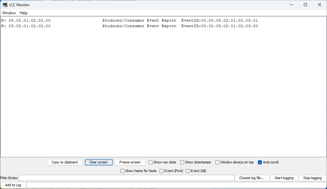
Figure: Button produces two distinct events - one for press, one for release
What you see:
Each button press/release cycle produces two events:
- Button pressed:
Produce Event: 00.00.05.02.01.02.03.01(Event Off) - Button released:
Produce Event: 00.00.05.02.01.02.03.00(Event On)
Note the naming:
- “Event On” occurs when GPIO goes HIGH (button released)
- “Event Off” occurs when GPIO goes LOW (button pressed)
This naming can be counterintuitive at first, but it’s consistent with the electrical state of the GPIO pin, not the physical button action. We’ll explain why later.
Viewing Button Configuration (Requires Restart)
Important: To view the updated button configuration in LccPro, you must restart the application to clear its cached CDI. The cache persists even if you refresh or close/reopen the Configure dialog.
After restarting, open the Configure dialog for your node:
- In LccPro, find your node:
async_blink - ESP32 Blink demo (05.02.01.02.02.00) - Right-click → Configure
- Scroll down to the Button 1 section
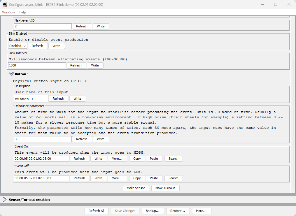
Figure: LccPro Configure dialog showing Button 1 configuration
What you see:
| Field | Default Value | Description |
|---|---|---|
| Description | Button 1 | User-editable name for this input |
| Debounce parameter | 3 | Number of 30ms cycles (90ms total) before state change confirmed |
| Event On | 00.00.05.02.01.02.03.00 | Produced when button is released (GPIO HIGH) |
| Event Off | 00.00.05.02.01.02.03.01 | Produced when button is pressed (GPIO LOW) |
Understanding Debounce
The debounce parameter controls how many consecutive polling cycles the input must remain stable before the event is produced. At 33Hz polling:
- Debounce = 3 (default): 3 cycles × 30ms = 90ms stabilization time
- Debounce = 2: 2 cycles × 30ms = 60ms (faster but less noise-immune)
- Debounce = 8: 8 cycles × 30ms = 240ms (very stable, good for noisy environments)
Typical values:
- 2-3: Good for clean pushbuttons in quiet environments
- 8-15: Recommended for train layouts with electrical noise from motors
Node Event IDs
Our node now produces multiple event IDs:
| Event | Offset | Full Event ID | Purpose |
|---|---|---|---|
| Async Blink 0 | +0x00 | 05.02.01.02.02.00.00.00 | Alternating event (state 0) |
| Async Blink 1 | +0x01 | 05.02.01.02.02.00.00.01 | Alternating event (state 1) |
| Button 1 ON | +0x0100 | 00.00.05.02.01.02.03.00 | Button released (HIGH) |
| Button 1 OFF | +0x0101 | 00.00.05.02.01.02.03.01 | Button pressed (LOW) |
Understanding Active-Low vs Active-High
The button in this example uses active-low logic:
- Physical button released → GPIO pin HIGH (3.3V via pull-up) → “Event On”
- Physical button pressed → GPIO pin LOW (0V to GND) → “Event Off”
Why Not Active-High (Pull-Down)?
You might reasonably ask: wouldn’t it be more intuitive if pressing the button produced “Event On” instead of “Event Off”? With active-high logic using a pull-down resistor, you could wire the button to 3.3V instead of GND:
- Physical button released → GPIO pin LOW (0V via pull-down) → “Event Off”
- Physical button pressed → GPIO pin HIGH (3.3V) → “Event On”
This would align the physical action (pressing) with the logical “On” state. And the ESP32 does have internal pull-down resistors (GpioInputPD) that would make this possible.
The OpenMRN/OpenMRNLite Bug
Unfortunately (as of December 2025), there’s a bug in OpenMRN’s ESP32 GPIO implementation that prevents using pull-down resistors on most pins. In the file Esp32Gpio.hxx, there’s a static assertion to prevent enabling pull-down on GPIO pins 0, 5, and 15 (which have hardware pull-ups on most ESP32 boards):
// GPIO 0, 5 and 15 typically have pull-up resistors.
static_assert(!PDEN ||
              (PDEN && (PIN_NUM != 0 && PIN_NUM != 5 && PIN_NUM == 15)),
              //                                           ^^
              // BUG: Should be != 15, not == 15
              "GPIO 0, 5, 15 typically have built-in pull-up resistors, "
              "enabling pull-down is not possible.");
The bug: The condition says PIN_NUM == 15 when it should say PIN_NUM != 15. This reversed logic means:
- Intended: Block pull-down on pins 0, 5, and 15
- Actual: Block pull-down on all pins except 15
When you try to use GpioInputPD on GPIO 18, you get a compile error:
error: static assertion failed: GPIO 0, 5, 15 typically have built-in
pull-up resistors, enabling pull-down is not possible.
This bug exists in both OpenMRNLite (the Arduino library) and the current master branch of OpenMRN (as of December 2025).
Why Use Pull-Up Anyway?
Even without the bug, active-low with pull-up is the standard pattern for pushbuttons in embedded systems:
- Noise immunity: Pull-up resistor provides a defined HIGH state when the button is open (not pressed)
- Simplicity: Button connects GPIO directly to GND—no need to route 3.3V to the button
- Safety: If a wire comes loose, the pin floats HIGH (safe idle state) rather than floating LOW
- Industry convention: Most schematics and examples use active-low buttons
So while the inverted logic (pressed = “off”) feels backwards at first, it’s actually the preferred approach independent of the OpenMRN bug.
Bottom line: We use GpioInputPU (pull-up) both because of the bug and because it’s best practice for button inputs.
Common Issues and Troubleshooting
Button events not appearing in JMRI/LccPro
Symptom: Traffic Monitor shows async_blink events but no button events.
Fixes:
- Verify wiring: One button pin to GPIO 18, other to GND
- Check CDI cache: Did you restart JMRI/LccPro after flashing?
- Test serial output: Does it show “GPIO initialized: Button on GPIO 18”?
- Verify factory reset: Check for “Button events: ON=…” in serial output
Button produces events continuously or erratically
Symptom: Traffic Monitor floods with button events without touching the button.
Possible causes:
- Loose connection: Check breadboard contacts and jumper wires
- Wrong pull-up/pull-down: Ensure you used
GpioInputPU(pull-up), notGpioInputPD - Electrical noise: Try increasing debounce from 3 to 8 or higher
- Floating pin: Verify GND connection is solid
Wrong event IDs in JMRI
Symptom: Button events show different IDs than expected.
Fixes:
- Factory reset required: Delete
/spiffs/openlcb_configand/spiffs/cdi.xml, then reboot - Node ID mismatch: Verify
NODE_IDin code matches what JMRI shows - Manual configuration: Someone may have changed Event On/Off in JMRI - restore defaults
What’s Next
You’ve successfully added a physical input to your OpenLCB node! The button can now:
- ✅ Produce unique events when pressed and released
- ✅ Be configured through JMRI/LccPro (description, debounce, event IDs)
- ✅ Operate reliably with hardware debouncing
In the next section, we’ll add LED outputs using ConfiguredConsumer so your node can respond to events from other nodes on the network—creating true two-way communication.
Complete Code Files
For reference, here are the complete updated files:
config.h (excerpt - button section)
 /// Version number for the configuration structure
-/// NOTE: Incremented to 0x0003 when adding blink_enabled and reserved space
-static constexpr uint16_t CANONICAL_VERSION = 0x0003;
+/// NOTE: Incremented to 0x0004 when adding button configuration
+static constexpr uint16_t CANONICAL_VERSION = 0x0004;

 /// Minimal configuration segment with application settings
 CDI_GROUP(AsyncBlinkSegment, Segment(MemoryConfigDefs::SPACE_CONFIG), Offset(128));
 CDI_GROUP_ENTRY(internal_config, InternalConfigData);
 CDI_GROUP_ENTRY(blink_enabled, Uint8ConfigEntry,
                 Default(1),
                 Min(0), Max(1),
                 MapValues(BOOLEAN_MAP),
                 Name("Blink Enabled"),
                 Description("Enable or disable event production"));
 CDI_GROUP_ENTRY(blink_interval, Uint16ConfigEntry,
                 Default(1000),
                 Min(100),
                 Max(30000),
                 Name("Blink Interval"),
                 Description("Milliseconds between alternating events (100-30000)"));
+CDI_GROUP_ENTRY(button, ProducerConfig,
+                Name("Button 1"),
+                Description("Physical button input on GPIO 18"));
 CDI_GROUP_END();
main.cpp (key additions)
 // ConfigDef comes from config.h and defines the configuration layout
 static constexpr openlcb::ConfigDef cfg(0);

+// Define GPIO pin for button input (active-low with internal pull-up)
+// When button is pressed, pin reads LOW (0); when released, reads HIGH (1)
+GPIO_PIN(BUTTON, GpioInputPU, 18);
+
+// GPIO initializer - sets up all GPIO pins before OpenMRN stack starts
+typedef GpioInitializer<BUTTON_Pin> GpioInit;
+
 // OpenLCB configuration - required by OpenMRNLite
 namespace openlcb {

...

 } factory_reset_helper;

+// Button producer - monitors GPIO 18 and produces events on state changes
+openlcb::ConfiguredProducer button_producer(
+    openmrn.stack()->node(), cfg.seg().button(), BUTTON_Pin());
+
+// RefreshLoop - polls button at 33Hz and handles debouncing
+openlcb::RefreshLoop button_refresh_loop(openmrn.stack()->node(),
+    {button_producer.polling()});
+
 void init_serial() {

...

     cfg.seg().blink_enabled().write(fd, 1);      // Default enabled
     cfg.seg().blink_interval().write(fd, 1000);  // Default 1 second

+    // Initialize button producer configuration
+    cfg.seg().button().description().write(fd, "Button 1");
+    cfg.seg().button().event_on().write(fd, NODE_ID + 0x0100);
+    cfg.seg().button().event_off().write(fd, NODE_ID + 0x0101);
+    CDI_FACTORY_RESET(cfg.seg().button().debounce);
+    Serial.printf("Button events: ON=0x%016llX, OFF=0x%016llX\n",
+                  NODE_ID + 0x0100, NODE_ID + 0x0101);
+
     Serial.println("Factory reset: wrote defaults...");

...

 void setup() {
   init_serial();
   init_filesystem();

+  GpioInit::hw_init();
+  Serial.println("GPIO initialized: Button on GPIO 18 (active-low with pull-up)");
+
   can_driver.hw_init();
   init_openlcb_stack();